IoT circuit board
An IoT circuit board is a printed circuit board used in a connected device. It supports and electrically connects components for sensing, processing, communication and power management, enabling the device to collect data and exchange it with other systems.
The board provides the electrical foundation. Firmware determines how the components operate, while a network connection carries data to another device, gateway or cloud service. A connected product needs these elements to work together.
A bare printed circuit board (PCB) contains conductive tracks and connection points. Once components are fitted and soldered, it becomes a printed circuit board assembly (PCBA), often referred to as an IoT circuit board when used in an IoT device.
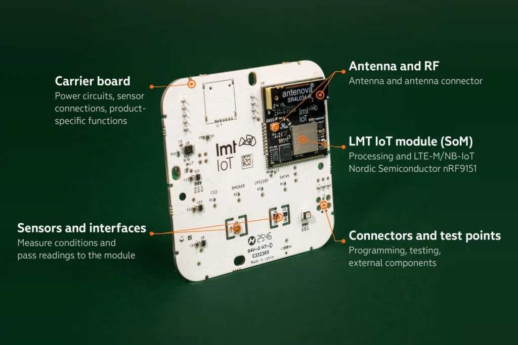
Main IoT circuit board components
An IoT circuit board can combine these functions in separate components or in an integrated module. The design depends on the device’s measurements, connectivity and power source.
| Component or circuit | Role in the device |
|---|---|
| Microcontroller and memory | Run firmware, process measurements and retain software, settings or buffered data. |
| Sensors and interfaces | Measure physical conditions or connect external sensors through digital or analogue inputs. |
| Communication hardware | Exchange data through technologies such as Bluetooth, Wi-Fi, Ethernet or cellular. |
| Antenna and RF circuitry | Transmit and receive radio signals in wireless designs. |
| Power management | Regulate supply voltage and manage batteries, charging or power switching where required. |
| Security hardware | Support functions such as cryptography and protected key storage when included in the design. |
| Connectors and test points | Connect external components and provide access for programming, testing and diagnosis. |
How the board works
Consider a battery-powered environmental sensor:
- The firmware wakes the device at a defined interval.
- A sensor measures a condition, such as temperature, and provides a reading to the microcontroller.
- The microcontroller checks or processes the reading and prepares a data message.
- The communication hardware sends the message to a gateway or directly over an available network.
- The device returns to a lower-power state until the next measurement or event.
A cloud service can then process and store the message for monitoring or integration. In a device with control functions, firmware may also receive a supported command and operate an output, such as a relay. The board must include the required circuitry for that action.
Types of IoT circuit board
Board construction affects size, mechanical fit, routing and manufacturing complexity.
| Construction | Typical use | Main consideration |
|---|---|---|
| Rigid PCB | Sensor units, gateways and equipment controllers | Component layout, enclosure fit and environmental protection |
| Flexible PCB | Compact products and connections that must follow an enclosure’s shape | Bend radius, material selection and expected flexing |
| Rigid-flex PCB | Products combining supported component areas with flexible interconnections | Mechanical design and more complex fabrication |
Layer count is a separate choice. Double-sided and multilayer boards provide different routing options. High-density interconnect, or HDI, uses fine features and microvias to fit dense circuits into limited space. These approaches can be combined with rigid or flexible construction.
Development boards are useful for evaluating components and firmware. A production board is designed around the final enclosure, power budget, assembly process and operating conditions. A system on module (SoM) can provide processing and connectivity, while a carrier board adds power circuits, sensor connections and product-specific functions.
IoT circuit design from requirements to production
IoT circuit design starts with the device’s job or intended use case. Define the measurements, reporting interval, operating environment, power source, connectivity and expected service life before selecting components.
- Select the architecture. Choose the processor or module, sensors, interfaces, power components and security functions. Check availability and development support.
- Create the schematic. Document electrical connections, voltage levels, protection circuits and programming access. Prepare the bill of materials.
- Design the PCB layout. Place components and route signals, power and ground. Follow the selected module’s antenna, RF and power-supply guidance.
- Review the design. Check electrical and layout rules, enclosure fit, assembly access and manufacturability with the production partner.
- Fabricate and assemble prototypes. Manufacture the bare boards, place and solder components, load firmware and check basic operation.
- Validate the complete device. Test sensing, communication, power use and behaviour across intended conditions. Use the results to refine the design before production.
- Prepare production testing. Define checks for assembled boards, firmware programming and device identities so faults can be detected consistently.
Power and radio design
Low-power operation depends on the complete board. Sensors, regulators, memory and indicator lights all contribute to consumption. Measure sleep, sensing, processing and transmission separately, then assess a full operating cycle under representative network conditions.
The supply must also handle the radio’s peak current without excessive voltage drop. Antenna placement, the ground plane and nearby enclosure materials affect radio performance. A small board or low sleep-current figure alone does not establish battery life.
Security in the hardware design
Select hardware that supports the security functions your product needs. A microcontroller with cryptographic acceleration or a separate secure element can support encryption, authentication and protected key storage. Firmware and manufacturing processes must use those functions correctly, including provisioning device credentials and checking software authenticity where supported.
Where are IoT circuit boards used?
The same building blocks support different connected products:
- Smart homes: temperature sensors, connected locks and controllers for lighting or heating.
- Wearables: compact motion and activity sensors that exchange readings with a phone or gateway.
- Healthcare: connected measurement devices that send readings to authorised monitoring systems.
- Industrial IoT: equipment-status, vibration and environmental sensors used to support maintenance.
- Automotive: telematics units and fleet sensors that report location or vehicle information.
The use case determines the required reliability, environmental testing and product qualification. A board suitable for a desk prototype may need substantial changes for a wearable, factory installation or vehicle.
Building connected devices with LMT
The LMT IoT module combines processing, LTE-M/NB-IoT connectivity and sensor interfaces. Your team can integrate it into a carrier board and develop sensor logic and product behaviour using the Zephyr-based software development kit.
The module is part of IoT Shortcut, which brings together hardware, firmware, connectivity and cloud services.
FAQ
Choose an IoT circuit board around the sensors’ voltage, interface, sampling rate and accuracy needs. Check the available I²C, SPI, UART, GPIO or analogue inputs, along with pin availability and firmware drivers. For several sensors, also check bus addresses, timing and power demand.
Evaluate an IoT circuit board in the complete product under its intended temperature, humidity, vibration and power conditions. Review component ratings, soldering quality, enclosure protection and supplier support. Define failure criteria and test representative units; service life cannot be inferred from the PCB material or a component rating alone.
In IoT circuit design, begin with the selected module’s reference schematic and hardware integration guide. Check supply voltage, peak current, antenna layout, SIM arrangements, interfaces and programming access. Test connectivity and power use in the final enclosure, and confirm which module approvals apply to the finished product.
Yes. An IoT circuit board can contain both, or use a module that combines processing and radio functions. Check whether the processor has enough memory, interfaces and software support to run your product logic. A separate host microcontroller may still be useful for an existing design or additional processing needs.
Choose interfaces that match the actual sensors. I²C and SPI commonly connect digital sensors, UART supports serial devices, and analogue inputs read suitable voltage signals. Check electrical levels, resolution and driver support as well as the interface name. External industrial sensors may require additional conversion or protection circuitry.