LMT Cellular LPWAN Extension Boards
A small add-on board that plugs into your Infineon AI Kit and gives it the ability to send data over cellular networks — like giving your device its own phone connection to the cloud. No Wi-Fi needed.
Seamless cellular connectivity for Infineon Edge AI Kits. Global SIM, serial-to-cloud gateway, pre-provisioned firmware — transmit AI-processed data from field to cloud with minimal development.
How it works
Your Infineon AI Kit processes sensor data with AI. This board adds the missing piece — sending that data to the cloud over cellular networks, anywhere in the world.
Sensors collect data
Temperature, motion, sound, vibration — your Infineon AI Kit reads the physical world through its sensors.
Edge AI processes it
The AI chip analyzes data right on the device. No cloud needed for the heavy computation. Decisions happen in milliseconds.
LMT board sends it
This extension board adds cellular connectivity. It transmits results over LTE-M / NB-IoT — works anywhere with cell coverage, no Wi-Fi needed.
You see it in the cloud
Data appears on your LMT IoT dashboard. Set up alerts, track trends, control devices remotely.
Wi-Fi
- Needs a router nearby
- Range: ~50 meters
- Indoor use mostly
- Requires network setup
Cellular (LTE-M)
- Works with cell coverage
- Range: kilometers
- Outdoor, remote, mobile
- Built-in SIM, zero setup
No expertise required
The board comes pre-configured. Built-in global SIM, pre-flashed firmware. Connect the antenna, write a few commands, power on. Data flows to the cloud.
What's included
Which board do I need?
 For Edge E84 AI Kit
Smaller board, simpler setup
For Edge E84 AI Kit
Smaller board, simpler setup
 For PSoC 6 AI Kit
More GPIO options, power protection
For PSoC 6 AI Kit
More GPIO options, power protection
Not sure which Infineon kit you have? Check the label on your board.
Specifications
Ordering
| Product # | Compatible Kit | Includes |
|---|---|---|
EBI151UFI |
Infineon PSoC Edge E84 AI Kit | Board + antenna + pin headers |
EBI251UFI |
Infineon PSoC 6 AI Kit | Board + antenna + pin headers |
Full Specifications
| Parameter | Value |
|---|---|
| Main modem / MCU | Nordic Semiconductor nRF9151 |
| Connectivity | LTE-M (Cat-M1) or NB-IoT (Cat-NB1/NB2) |
| SIM configuration | Global MFF2 SIM included + nano-SIM slot |
| Deep sleep current | <8 μA at 3.6V |
| Single upload energy | 90 mJ / 25 μWh (100B payload) |
| Antenna | Molex 824–2170 MHz flexible, U.FL (included) |
| Firmware updates | FOTA (LMT module only) |
| Firmware | Pre-flashed, pre-provisioned to your cloud account |
Board Variants
Two variants available — one for each supported Infineon AI Kit.
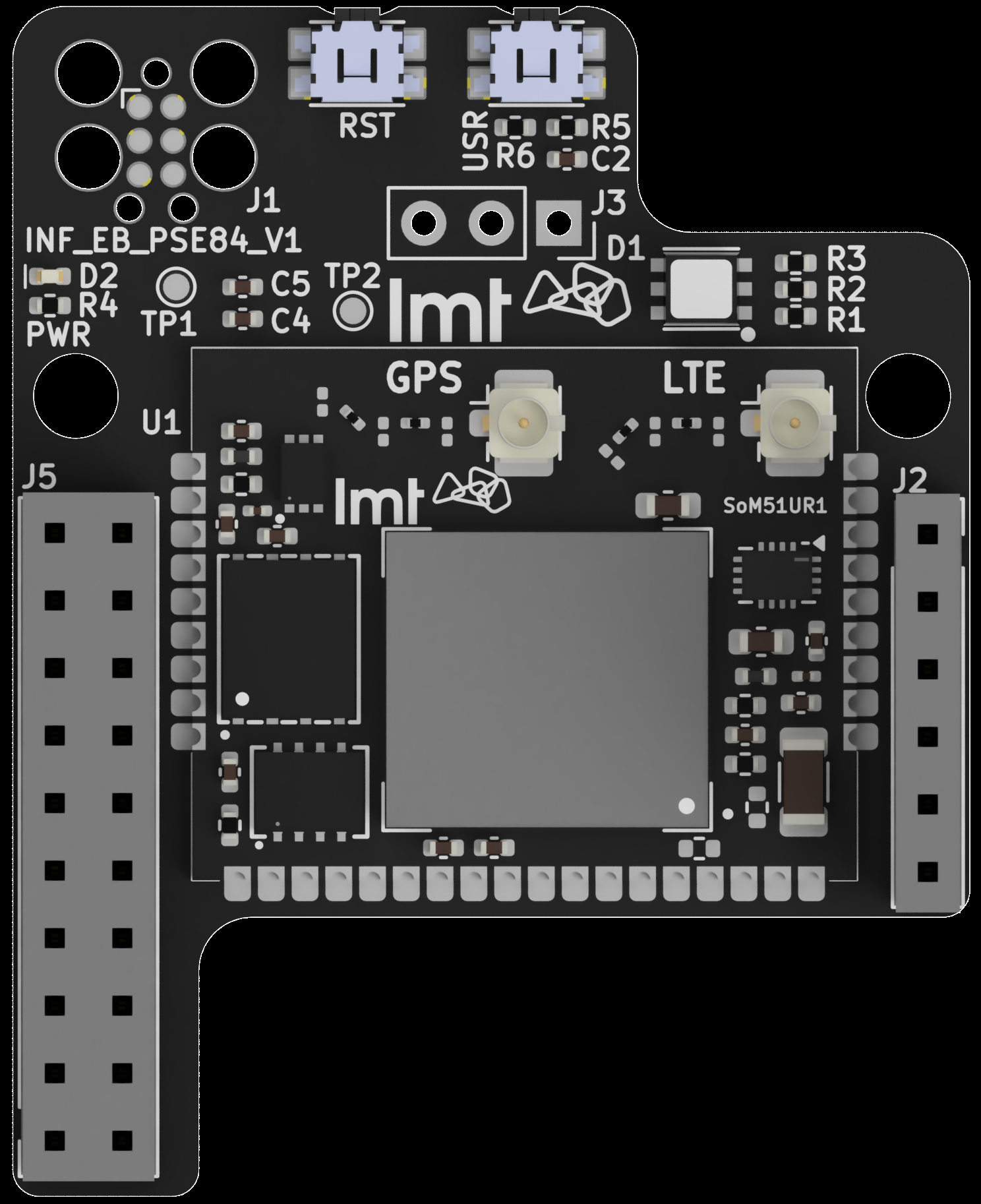
EBI151UFI — Edge E84 Board
Board Diagram
Components
Pinout
Connections between the Infineon host board, LMT SoM, and user-accessible I/O:
| Header | Infineon Side | LMT SoM Side | Function |
|---|---|---|---|
J5 | UART TX | UART RX | Serial data → LMT |
J5 | UART RX | UART TX | Serial data ← LMT |
J5 | GND | GND | Ground reference |
J5 | VDD | VDD | Power supply |
J1 | — | nRESET | Tag-Connect: reset |
J1 | — | SWDIO | Tag-Connect: debug data |
J1 | — | SWDCLK | Tag-Connect: debug clock |
| TP | — | VDD | Test point: power output |
| TP | — | GND | Test point: ground |
Design Notes
- All unmarked header pins are electrically isolated pass-through connections
- Power indicator LED across VDD/GND confirms active state
- Tag-Connect: use
TC2030-CTXorTC2030-CTX-NL(space-saving)
Dimensions
44.75 × 35.99 mm — 2× Ø3.2 mm mounting holes
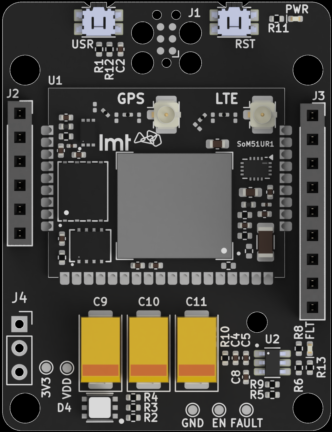
EBI251UFI — PSoC 6 Board
Board Diagram
Components
Power Protection
- Extended cellular TX (large payloads) can exceed the limit — buffering capacitors absorb transient spikes
- On short-circuit: power disconnected immediately, fault LED illuminates, auto-recovery after brief delay
- Bridge
JP8to route FAULT signal to Infineon P9.0 - Test points:
3V3(raw supply) andVDD(after power limiter)
Pinout — J2 Header (Infineon PSoC side)
| Pin | Infineon | LMT SoM | Bridge | Function |
|---|---|---|---|---|
| 1 | VDD | VDD | — | Power supply |
| 2 | GND | GND | — | Ground |
| 3 | P5.0 | GPIO_1 | JP1 | Configurable I/O |
| 4 | P5.1 | GPIO_2 | JP2 | Configurable I/O |
| 5 | P5.2 | GPIO_3 | JP3 | Configurable I/O |
| 6 | P5.3 | GPIO_4 | JP4 | Configurable I/O |
| 7 | P9.0 | FAULT | JP8 | Power fault signal |
| 8–12 | Pass-through (electrically isolated) | — | ||
Pinout — J3 Header (Infineon PSoC side)
| Pin | Infineon | LMT SoM | Bridge | Function |
|---|---|---|---|---|
| 1 | P6.0 (TX) | UART RX | — | Serial data → LMT (default) |
| 2 | P6.1 (RX) | UART TX | — | Serial data ← LMT (default) |
| 3 | P6.2 | GPIO_5 | JP5 | Configurable I/O |
| 4 | P6.3 | GPIO_6 | JP6 | Configurable I/O |
| 5 | P6.4 | GPIO_7 | JP7 | Configurable I/O |
| 6–10 | Pass-through (electrically isolated) | — | ||
Pinout — J1 Connector (Tag-Connect)
| Pad | LMT SoM | Function |
|---|---|---|
| 1 | VDD | Power reference |
| 2 | SWDIO | Debug data |
| 3 | nRESET | Module reset |
| 4 | SWDCLK | Debug clock |
| 5 | GND | Ground |
Solder Bridges (JP1–JP8)
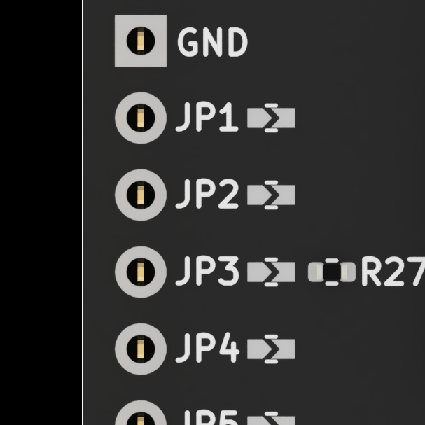
JP1–JP8 on board back
| Jumper | Infineon | LMT | Notes |
|---|---|---|---|
JP1 | P5.0 | GPIO_1 | General purpose |
JP2 | P5.1 | GPIO_2 | General purpose |
JP3 | P5.2 | GPIO_3 | General purpose |
JP4 | P5.3 | GPIO_4 | General purpose |
JP5 | P6.2 | GPIO_5 | General purpose |
JP6 | P6.3 | GPIO_6 | General purpose |
JP7 | P6.4 | GPIO_7 | General purpose |
JP8 | P9.0 | FAULT | Power fault readback |
Dimensions
Board dimensions and mounting hole positions.
E84 Board (EBI151UFI)
| Width | 44.75 mm |
| Height | 35.99 mm |
| Mounting holes | 2× Ø3.2 mm, 14.65 mm spacing |
| Corner radii | 5× R2, 3× R1 |
| Board thickness | ~2.35 mm (with components) |
PSoC 6 Board (EBI251UFI)
| Form factor | Matches PSoC 6 AI Kit footprint |
| Mounting | 4× corner mounting holes |
| Capacitors | 3× bulk caps (C9, C10, C11) for TX current buffering |
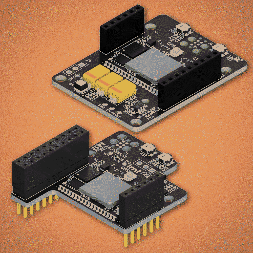
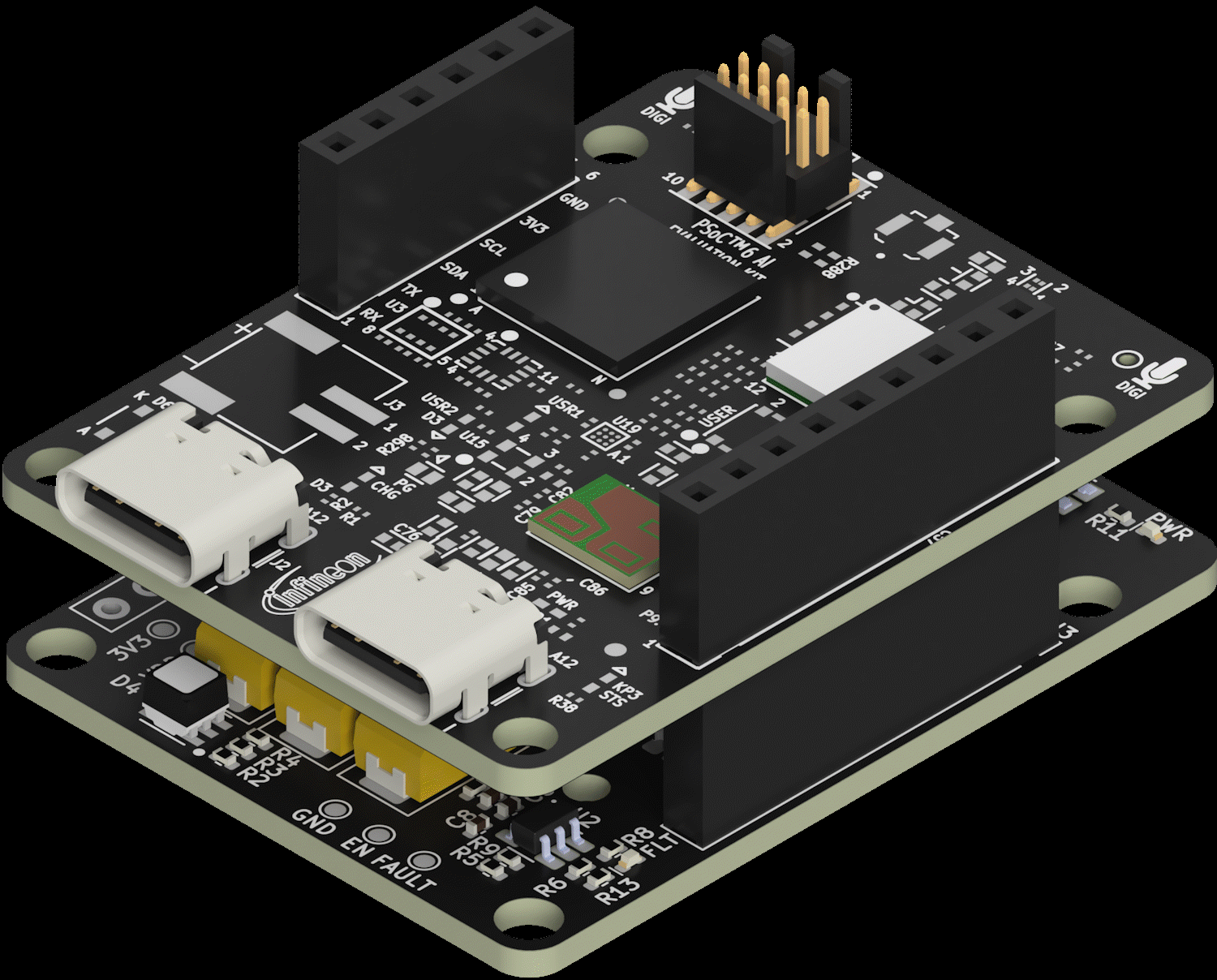
Setup in 3 steps
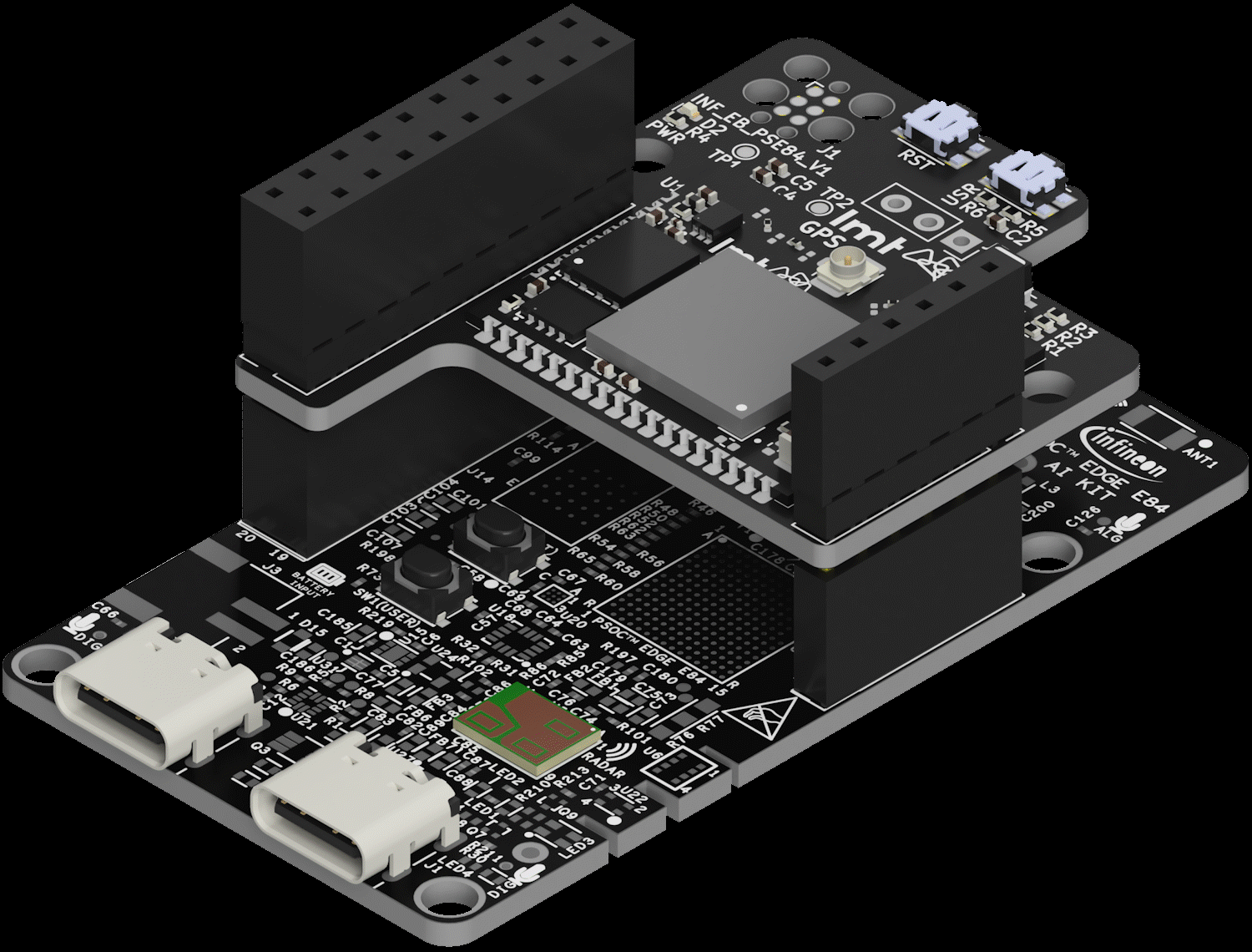
This is what it looks like assembled
Board plugs right on top
What if something doesn't work?
The board has a debug port you can connect to see what's happening. There's also a reset button and status LEDs that tell you the connection state. Switch to Technical mode for detailed troubleshooting.
Setup Guide
Three phases: cloud configuration, firmware development, and hardware mounting.
1. Cloud Configuration
Verify Cloud Registration
Your device is pre-provisioned to your LMT IoT Cloud account. Verify it appears in your device list.
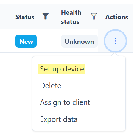
Actions → Set up device
Configure Data Payload
Define the structure of transmitted data using the configuration wizard. Set up CoAP protocol tracks for incoming messages.
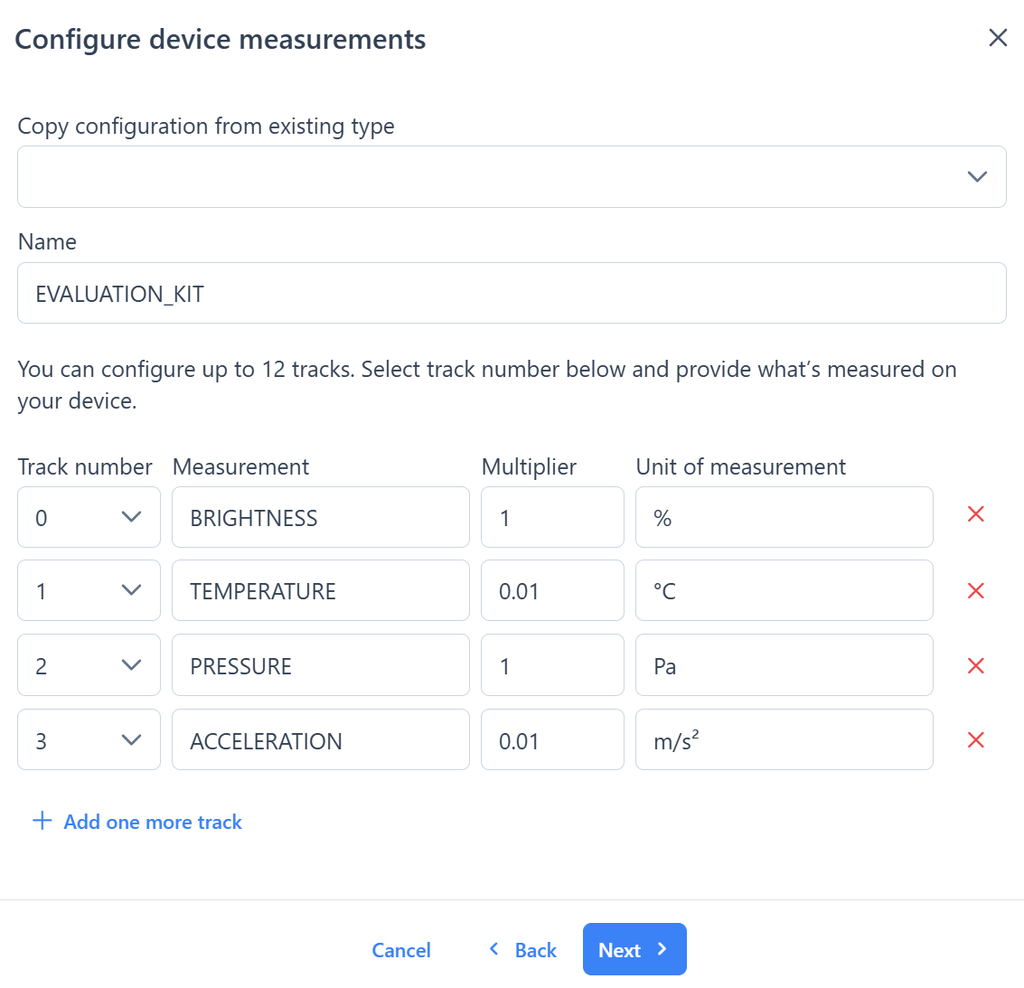
Configure tracks: measurement name, multiplier, unit
2. Firmware Development
Implement the "serial-to-cloud gateway" commands in your host Infineon firmware. Ensure the data packet format matches the cloud configuration.
3. Hardware Mounting
Prepare the Extension Board
Connect the U.FL cellular antenna to the port labeled LTE. For the EBI251UFI: bridge any needed solder pads before mounting.
Solder Pin Headers
Solder the included female pin headers onto the Infineon PSoC AI Kit. Both sides are needed for proper mechanical support.
Mount & Power On
Flash your firmware onto the host board. Mount the LMT extension board. Apply power and verify data uploads in the cloud dashboard.
Assembly Result
E84 Kit — assembled
PSoC 6 Kit — assembled
Troubleshooting
| Issue | Tool | Action |
|---|---|---|
| No data in cloud | UART debug header | Inspect serial communication between host and LMT module |
| Custom button/LED behavior | Tag-Connect pads | Reflash LMT module firmware via TC2030-CTX |
| Fault LED illuminated | Test points | Measure 3V3 vs VDD — check for short circuit |
| No cellular connection | Antenna | Verify U.FL connected to LTE port (not GPS) |
| Custom SIM not working | SDK docs | Toggle active SIM via SDK commands |
© 2026 LMT IoT. Datasheet v1.1 (2026-04-13)